sphinx-quickstart on Tue Mar 28 19:35:56 2017. You can adapt this file completely to your liking, but it should at least contain the root toctree directive.
Welcome to iot-ledmatrix’s documentation!
iot-ledmatrix is the code written by enra64 and gSilas to use their DIY IOT WS2812B RGB LED matrix.
If you want to build a similar project, feel free to use any of our source code. It is licensed under GPL v3. If you are so inclined, you can even use the complete code base and add any functionality you desire using our custom script interface.
The code consists of three parts:
- the python code used on the raspberry pi inside the matrix
- the android code making up the control app
- the arduino code required to talk to the leds
This documentation is mostly concerned with the python code used on the rpi, since at the moment the other code is only written by enra64 and not really subject to change.
Raspberry pi (host) code
The raspberry pi code is responsible for pushing the correct colors to the arduino, and also constitutes the bridge between the matrix, the internet and an optional android phone.
architecture
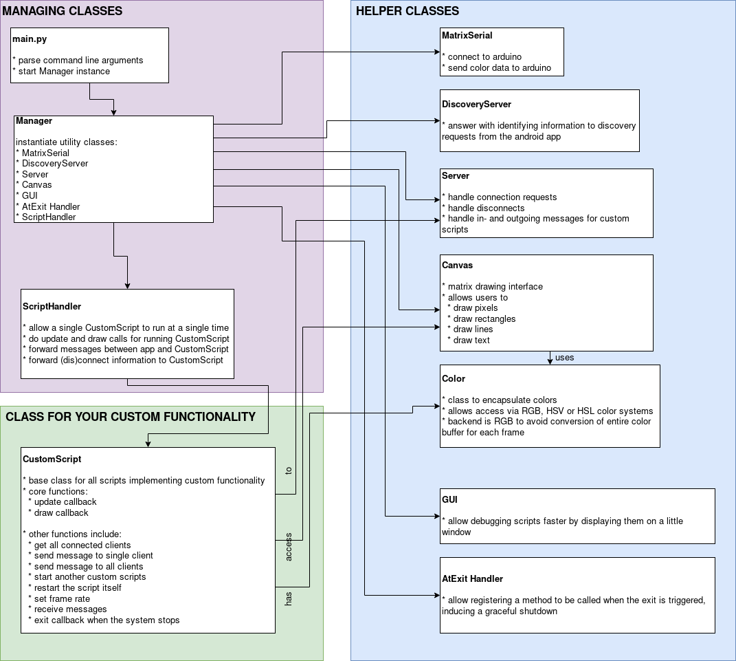
An overview of the architecture used by the host code
If you’re like me, you like to have some semblance of an idea of how the code is structured, so here is an architecture diagram to show exactly that.
custom scripts
Custom scripts enable you to easily create new features for the matrix. They are discussed in detail here: Custom scripts
how to get it running on your raspberry pi
get some required packages: :code:`sudo apt update && sudo apt install git python3-pip `
download the code using git clone for easy updating:
git clone https://github.com/enra64/iot-ledmatrix.gitinstall the required packages:
sudo pip3 install -r iot-ledmatrix/host/requirements.txtset up avahi to advertise your matrix in the local network:
sudo nano /etc/avahi/services/ledmatrix.service:<?xml version="1.0" standalone='no'?><!--*-nxml-*--> <!DOCTYPE service-group SYSTEM "avahi-service.dtd"> <service-group> <name replace-wildcards="no">My Matrix:10:8</name> <service> <type>_iot-ledmatrix._tcp</type> <port>55124</port> </service> </service-group>run with python3:
/usr/bin/python3 /home/pi/iot-ledmatrix/host/main.py --name="My Matrix" --width=10 --height=8 --logfile=/home/pi/matrix.log --keepalive --loglevel=DEBUG >> /home/pi/output_matrix.log- For autostart: add a systemd unit and create a startup script:
nano /home/pi/start_wakeuplight_systemd.sh, adapt the following template:#!/bin/bash /usr/bin/git -C /home/pi/iot-ledmatrix pull >> /home/pi/git_pull_log /usr/bin/python3 /home/pi/iot-ledmatrix/host/main.py --name="My Matrix" --width=10 --height=8 --logfile=/home/pi/matrix.log --keepalive --loglevel=DEBUG >> /home/pi/output_matrix.log
sudo nano /etc/systemd/system/ledmatrix.service, adapt the following template to your need (command line options):[Unit] Description=My iot-ledmatrix Requires=network.target [Service] Type=idle User=root ExecStart=/usr/bin/bash /home/pi/start_wakeuplight_systemd.sh Restart=no [Install] WantedBy=multi-user.target
enable & start the service to see your ledmatrix working
sudo systemctl enable ledmatrix.service && sudo systemctl start ledmatrix.service
Note: If you are using /dev/ttyAMA0 (serial0) for the Arduino you may have to remove this serial port from /boot/cmdline.txt as the Pi will print its boot messages to this port.
android code
The android app included in client-android makes working with the matrix really easy. It supports some administration features, and it is the basis for interactive scripts.
administration
Users can reboot the raspberry pi, shut it down or simply restart the host code. A log viewer is also implemented, so failures can be quickly debugged.
host script fragments
Programmers can write Fragments that display an arbitrary user interface to implement any required custom functionality. Two-Way communication with the matrix is available.
arduino sketch
The arduino code is simple, but NUM_LEDS_CURRENT must be set before uploading the code.
The arduino will partake in a simple handshake to confirm correct initialization.
After that, the arduino writes all received data into the led buffer.
Whenever enough bytes for a single frame have arrived, the leds will show the new data.